Ultrasonic testing for welds, wall thickness and corrosion
Ultrasonic testing sends high frequency sound into a material and listens for what comes back. Reflections from a crack, a lamination or the far wall arrive at measurable times, so UT tells you not only that something is there but how deep it sits and, with the right technique, how tall it is. That makes it the workhorse for weld volume inspection, remaining wall thickness and corrosion monitoring on plants, pipelines and structures. Here is how the main techniques differ and how to scope a job.
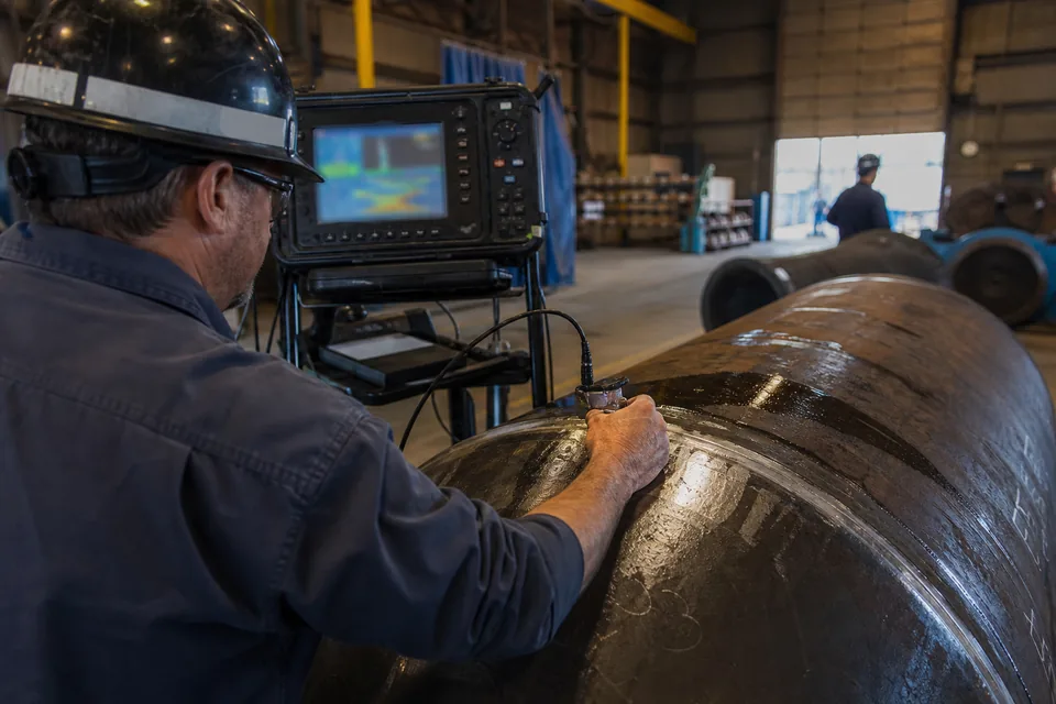
UT testing techniques and what each is for
- Conventional pulse echo UT: a single element probe, straight beam for thickness and laminations, angle beam for welds. Flexible, portable and inexpensive, but results depend heavily on the operator.
- Phased array ultrasonic testing (PAUT): an array probe steers and focuses the beam electronically, producing sector and linear scans. Encoded scans create a permanent, reviewable record of the weld.
- Time of flight diffraction (TOFD): two probes pick up signals diffracted from flaw tips, which gives accurate through wall height sizing. Often paired with PAUT for full weld coverage.
- Ultrasonic thickness gauging: spot readings of remaining wall on piping, vessels and tanks, the basis of many corrosion monitoring programs.
- Immersion UT and C-scan: the part sits in a water tank while a probe rasters over it, producing a plan view map. Common for aerospace forgings, composites and bonded structures.
- Corrosion mapping: encoded scanners record thickness over an area as a color map, so you see the shape and depth of wall loss rather than a few points.
What ultrasonic testing finds
- Planar weld flaws: cracks, lack of sidewall fusion, incomplete penetration, with depth and length.
- Volumetric weld flaws such as slag and larger porosity, though RT often images these more clearly.
- Remaining wall thickness, internal corrosion, erosion and pitting from the outside surface.
- Laminations and inclusions in plate and forgings.
- Disbonds and delaminations in composites and bonded joints, typically with immersion or phased array C-scan.
- Hydrogen damage and certain forms of cracking in refinery equipment when advanced techniques are applied.
Where UT struggles
- Coarse grained materials such as austenitic stainless welds and cast stainless, where grain scatter adds noise unless special probes are used.
- Very thin sections and complex geometry where the beam cannot be placed cleanly.
- Rough or coated surfaces that limit coupling, without surface preparation.
- Small, scattered porosity, which radiographic testing usually images better.
- Surface breaking cracks on the scanning surface, often better confirmed with magnetic particle inspection or eddy current testing.
Industries and assets
UT is everywhere metal carries pressure or load. Refineries and chemical plants run thickness monitoring under API 570 for piping and API 510 for vessels, and tank floors and shells are checked under API 653. Fabrication shops and construction projects use angle beam and PAUT for welds under ASME and AWS D1.1. Power plants inspect boiler tubes, headers and turbine components. Aerospace uses immersion UT on forgings and composites. Pipelines rely on PAUT and AUT for girth welds and on corrosion mapping at digs. See oil and gas inspection services and power plant inspection services for sector specific notes.
UT weld inspection and phased array ultrasonic testing on welds
Many construction codes allow UT in place of radiography when it is performed with qualified procedures. ASME Section V Article 4 covers UT of welds, and ASME code cases and Section VIII rules govern when UT can replace RT and with what acceptance criteria. AWS D1.1 includes its own UT clauses for structural steel. PAUT and TOFD avoid radiation exclusion zones, so other trades keep working, and encoded data can be audited later. The trade off is the need for a written, often demonstrated procedure and well qualified operators, because flaw characterization relies on interpretation.
How a UT job runs
- You describe the component: material, thickness, geometry, access, temperature and the question (weld acceptance, minimum wall, corrosion extent).
- The provider selects technique and writes or confirms the procedure, including calibration blocks, probes and scan plan.
- Surface preparation is agreed: removing loose scale or coating where needed.
- Technicians scan on site or in the lab. Encoded PAUT, TOFD and corrosion mapping data are saved for review.
- A Level II or Level III analyst evaluates indications against acceptance criteria or computes remaining wall.
- You receive a report with locations, sizes, thickness grids or C-scan maps and accept or reject calls.
Thickness surveys and conventional weld checks often finish within the visit. Advanced data analysis and reporting usually adds 2 to 5 business days.
What drives ultrasonic testing cost
Field UT is usually priced by technician day rate, with a higher rate for PAUT, TOFD and corrosion mapping because of equipment and data analysis. Access is the big variable: scaffolding, insulation removal, rope access and confined space entry can cost more than the inspection itself. Lab immersion work is priced per part or per hour after a fixture and scan plan exist.
| Job type | Typical range, not a quote |
|---|---|
| Conventional UT technician, per day | $800 to $1,600 |
| PAUT or TOFD technician with equipment, per day | $1,500 to $3,200 |
| Thickness gauging survey, small plant circuit | $500 to $1,500 |
| Corrosion mapping, per day including data | $1,600 to $3,500 |
| Immersion C-scan in a lab, per part | $150 to $1,200 |
Mobilization, travel, per diem and access costs are usually extra.
What to put in an ultrasonic testing services request
- 01Material, thickness, diameter for pipe, weld type and joint geometry.
- 02Technique required or allowed: conventional, PAUT, TOFD, thickness gauging, corrosion mapping, immersion.
- 03Governing code and acceptance criteria (ASME, AWS D1.1, API 1104, API 570, API 510, API 653 or a customer spec).
- 04Quantity: number of welds, thickness locations or square feet to map.
- 05Access and conditions: height, insulation, coating, surface temperature, confined space.
- 06Deliverables: report, thickness grids, encoded data files and viewer.
Certifications to ask a UT provider for
Ask for UT Level II personnel for the specific technique, since a conventional UT certification does not cover PAUT or TOFD. For refining and petrochemical work, owners often require API QUTE for thickness and API QUPA for phased array flaw sizing, alongside API 510, 570 or 653 inspector involvement. Aerospace work calls for NAS 410 personnel and NADCAP accreditation covering ultrasonic. For lab testing, check that UT sits inside the ISO/IEC 17025 scope. Ask whether procedures have been demonstrated or qualified for your thickness range and material.
FAQ
What is the difference between UT and PAUT?
Conventional UT uses a single element and one beam angle at a time. PAUT uses many elements to steer and focus the beam, covers more volume per pass and produces images that can be recorded and reviewed later.
Can ultrasonic testing replace radiography?
Often, when the governing code permits it and a qualified procedure is used. PAUT with TOFD is widely used in place of RT on thicker welds, and it avoids radiation exclusion zones.
How accurate is ultrasonic thickness gauging?
On clean, parallel surfaces with proper calibration, readings are typically within a few thousandths of an inch. Pitting, rough surfaces and coatings reduce accuracy, which is why corrosion mapping is used for detailed assessment.
Does UT work through paint or coating?
Some gauges use echo to echo mode to measure metal thickness through thin coatings. Flaw detection usually needs the coating removed or a technique qualified for the coating.
Can UT inspect composites?
Yes. Immersion and phased array C-scans are standard for finding delaminations, porosity and disbonds in carbon fiber and glass fiber laminates.
From part description to matched UT quotes
The inspection method advisor compares UT with radiography, eddy current and other options for your material and concern, notes when PAUT or TOFD makes sense, and gives a typical turnaround and a typical price band labeled as an estimate. The output is an RFQ with technique, code and coverage spelled out, sent to matched providers after you create your account and confirm your email. Read how to get NDT quotes for the full flow.
- 01What needs inspecting
- ...
- 02Material
- ...
- 04Concern
- ...
Run an ultrasonic testing service? List your company
List your techniques, procedures and certifications and receive matched UT, PAUT and thickness survey requests. See plans for NDT labs.