How 2D radiography works on castings
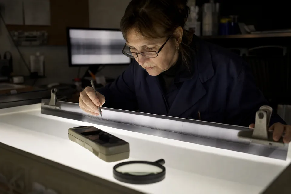
In radiographic testing an X-ray source sends radiation through the casting onto a detector: film, a phosphor plate (computed radiography) or a flat panel (digital radiography). Thicker or denser regions absorb more radiation. A pore removes material along the beam path, so it shows as a darker spot. Inspectors grade the image against reference radiographs such as ASTM E155 for aluminum and magnesium castings or ASTM E446 for steel castings, or against a drawing note. Real time systems in foundries can inspect a casting in seconds to a few minutes from several angles.
How industrial CT works on castings
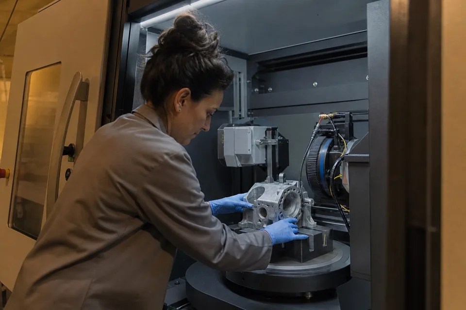
Industrial CT scanning records hundreds or thousands of radiographs while the casting rotates and reconstructs them into a 3D volume. Every voxel holds a density value, so software can segment pores, measure each one, map them by location and report porosity as a percentage of a region. The same data supports wall thickness analysis and nominal to actual comparison against the CAD model. A typical scan takes from several minutes to a few hours depending on size, material and resolution.
CT vs X-ray inspection side by side
The table compares the two methods for typical aluminum and steel castings.
| Factor | 2D radiography | Industrial CT |
|---|---|---|
| Output | 2D projection images | 3D volume, slices, measurements |
| Pore location in depth | Not directly, needs extra views | Exact 3D position |
| Pore size and volume | Approximate, projected area | Measured per pore, volume percent by region |
| Planar cracks | Visible only near beam direction | Better, still limited by voxel size and orientation |
| Wall thickness and core shift | Indirect | Measured across the part |
| CAD comparison | No | Yes, color deviation maps |
| Speed per part | Seconds to minutes | Minutes to hours |
| Typical cost per part, typical range, not a quote | $25 to $150 | $300 to $2,500 |
| Typical use | Production acceptance, grading to reference standards | First article, process development, failure analysis |
Porosity and shrinkage in castings
Both methods detect gas porosity and shrinkage when the void is large enough relative to the section thickness. Radiography shows the projected outline, which works well for grading against reference images but can overlap pores at different depths into one larger indication. CT separates them and measures each one, which matters when acceptance depends on porosity near a sealing surface, a bolt hole or a machined face. Many casting drawings now call out zones with different allowable porosity, and that kind of zoned acceptance is much easier to verify with CT data.
Cracks, cold shuts and inclusions
Hot tears and cracks are planar. On a radiograph they appear only when they lie close to parallel with the beam, so they can be missed in one view. CT sees them from all angles, but a very tight crack can still be smaller than the voxel size and vanish into the noise. For surface breaking cracks, liquid penetrant testing on aluminum or magnetic particle inspection on ferrous castings is often more sensitive and much cheaper than either X-ray method. Dense inclusions show well on both; low density inclusions such as sand or oxide films are harder and depend on contrast.
Porosity exposed by machining
A pore that sits a fraction of a millimeter below a machined face is harmless in the raw casting and becomes a leak path after machining. Radiography cannot tell you how close the pore is to the future machined surface without extra views and careful interpretation. CT measures the distance from each pore to the surface directly, and some labs can overlay the machining allowance from the CAD model to flag pores that machining will open. For pressure tight housings and hydraulic bodies this one capability often justifies CT on first articles.
Geometry problems
Core shift, thin walls, blocked passages and missing features are geometric faults rather than voids. Radiography can hint at them; CT measures them. If the casting has internal cooling or hydraulic channels, CT is usually the only practical way to verify them without cutting the part. For external geometry only, 3D scanning services can be a cheaper option.
Detection limits for CT and X-ray on castings
Detection limits depend on material, section thickness, equipment and setup, so treat any single number with caution. On radiographs, a common rule of thumb is that a void needs a size of roughly 1 to 2 percent of the penetrated thickness to show reliably, which is why image quality indicators are placed on every exposure to prove sensitivity. In CT, a feature generally needs to span at least two to three voxels to be detected and more to be measured with confidence. A casting scanned at a voxel size of 100 micrometers will therefore show pores of a few tenths of a millimeter, while pores smaller than that may be missed or only partly segmented. Ask every provider to state the smallest pore they can detect on your alloy and thickness, and how they demonstrated it.
Material and size limits
Aluminum and magnesium castings are easy targets for both methods because they absorb little radiation. Steel, cast iron and nickel alloy castings need higher energy sources, longer exposures and, for CT, larger systems. Many service bureaus can scan aluminum housings of several hundred millimeters, while dense steel castings of the same size may need a high energy system that fewer providers own. Radiography has fewer size limits because the source and detector can be positioned around the casting, including on site at a foundry. If your castings are large or dense, check the provider's stated CT envelope before you plan a CT program around it.
Cost in context
Per part, CT costs several times more than 2D radiography. Per decision, it can cost less. One CT scan that shows a shrinkage cavity sits in a non critical boss can save a lot of scrapped castings that a conservative radiographic grade would have rejected. One scan that shows porosity breaking into a sealing face can stop a leak problem before parts ship. Weigh the inspection price against the value of the decision, not against the price of the other method.
When 2D radiography is enough
Choose radiography when the question is accept or reject against a known standard and you need to inspect many parts.
- Production acceptance where the drawing or customer specification refers to reference radiographs
- Stable processes where the defect types and locations are already known
- High volume parts where cost and speed per part matter most
- Large or dense castings beyond the envelope of an available CT system
- Weld repairs on castings that need radiographic acceptance under a code
When CT pays for itself
Choose CT when the extra information changes a decision or saves scrap.
- First article inspection and PPAP for new casting designs or new tooling
- Process development: gating, venting, die temperature or pour changes
- Zoned porosity acceptance near sealing or machined surfaces
- Root cause analysis of leaks or field failures
- Verifying internal channels, wall thickness and core position
- Inspecting castings for safety critical or aerospace applications where the drawing calls for volumetric data
A combined approach for casting programs
Many foundries and buyers use both. CT on first articles and on a few parts per lot builds a map of where defects form and whether they matter. Radiography then covers routine production at a lower cost per part. When radiography flags a borderline indication, a CT scan of that casting settles it with measurements instead of debate. For the budget side, see industrial CT scanning cost and NDT inspection cost, and for industry specific practice see casting inspection services.
What to include in a casting inspection request
The same request structure works for both methods.
- Alloy, casting process (die, sand, investment, permanent mold), dimensions, weight and max wall thickness
- Number of castings now and per month
- Purpose: first article, production acceptance, failure analysis or process development
- Acceptance criteria: reference radiograph grade, porosity class, zoned limits or drawing notes
- Regions of interest marked on a drawing or CAD file
- For CT: required voxel size or smallest pore to detect, analyses needed (porosity, wall thickness, CAD comparison)
- Report format, image or data deliverables and turnaround
- Certifications required as stated by the provider, such as ISO 17025 scope or NADCAP for aerospace castings
Questions to ask the inspection provider
A few direct questions reveal whether the provider fits the job.
- What is the smallest pore you reliably detect on this alloy and section thickness?
- For radiography, how many views per casting, and do you grade to the reference standard I specified?
- For CT, which system will scan the part and at what voxel size, and how many scans are needed?
- How is porosity segmented and what threshold do you use?
- Who signs the report, and what is their NDT qualification level?