The ten methods at a glance
Use this table as a first filter. The sections below explain each method in more detail.
| Method | Physical principle | Finds best | Main limit |
|---|---|---|---|
| Industrial CT | X-ray projections reconstructed in 3D | Internal porosity, voids, geometry | Part size and density, cost per part |
| Radiography (RT, DR, CR) | X-ray or gamma absorption on a 2D image | Volumetric flaws in welds and castings | Planar cracks at the wrong angle, radiation safety |
| Ultrasonic (UT, PAUT, TOFD) | Reflection of high frequency sound | Planar flaws, lack of fusion, wall thickness | Coarse grain, complex geometry, operator skill |
| Magnetic particle (MT) | Flux leakage at surface flaws | Surface and near surface cracks in steel | Ferromagnetic only |
| Liquid penetrant (PT) | Capillary action into open flaws | Surface breaking cracks on most solids | Open to surface only, needs clean surface |
| Eddy current (ET) | Induced currents in conductors | Surface cracks, tube wall loss, conductivity | Shallow depth, conductors only |
| Infrared thermography | Surface temperature patterns | Hot electrical joints, insulation loss, delamination | Surface view only, needs a heat difference |
| Visual and borescope | Direct or remote optical view | Visible damage inside engines, pipes, cavities | Only what the camera can reach and see |
| Drone inspection | Cameras and sensors on a UAV | Blade, roof, tower and line damage at height | Weather, airspace rules, surface only |
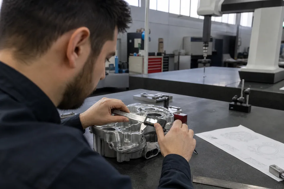
| 3D scanning | Laser or structured light surface capture | Shape deviation, wear, reverse engineering | External surfaces only |
Industrial CT scanning
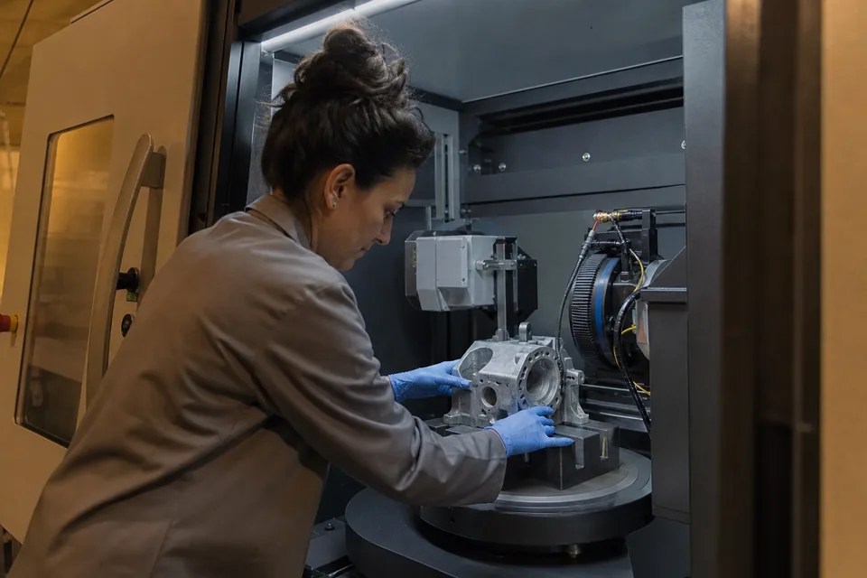
Industrial CT scanning takes hundreds or thousands of X-ray projections while the part rotates and reconstructs a 3D volume. You can slice it in any direction, measure porosity by size and location and compare internal and external geometry to CAD. Resolution depends on part size: small parts can reach voxel sizes of a few micrometers, while large castings typically land between roughly 50 and 200 micrometers. CT suits castings, additive parts, electronics, batteries and assemblies. It struggles with large, dense steel parts and costs more per part than 2D radiography.
- Finds: porosity, shrinkage, inclusions, internal geometry, assembly errors
- Misses or struggles: very tight cracks below voxel resolution, large dense parts beyond the system envelope
Radiographic testing
Radiographic testing projects X-rays or gamma rays through the part onto film, a phosphor plate (CR) or a digital detector (DR). Denser or thicker regions absorb more radiation, so voids and inclusions show as darker areas. It is the classic method for weld acceptance under ASME and AWS codes and for casting grading against ASTM reference radiographs. Planar cracks show only when they lie roughly parallel to the beam.
- Finds: porosity, slag, incomplete penetration, shrinkage, missing or misplaced components
- Misses or struggles: tight cracks at an angle to the beam, depth position without extra shots
Ultrasonic testing and phased array
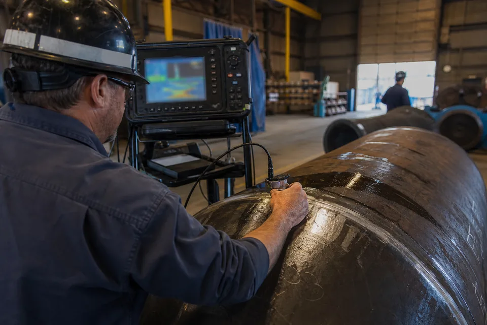
Ultrasonic testing sends sound pulses into the material and reads the echoes. Conventional UT uses one element. Phased array (PAUT) steers and focuses many elements and builds sectional images. Time of flight diffraction (TOFD) sizes cracks by their tip signals. UT is the preferred method for planar flaws such as lack of fusion and cracks, for thickness gauging and for corrosion mapping. It needs a couplant, a trained operator and a calibration block that matches the material.
- Finds: lack of fusion, cracks, laminations, wall loss, bond problems in composites
- Misses or struggles: coarse grained austenitic welds and cast stainless, thin or very complex shapes
Eddy current testing
Eddy current testing uses an alternating magnetic field to induce currents in a conductor. Cracks, corrosion and changes in conductivity disturb those currents. It is fast, needs little surface prep and works through thin paint. Typical uses include aircraft structure around fasteners, heat exchanger and condenser tubing, and sorting alloys by conductivity.
- Finds: surface and near surface cracks, tube wall loss and pitting, conductivity and coating thickness
- Misses or struggles: deep subsurface flaws, non conductive materials
Magnetic particle inspection
Magnetic particle inspection magnetizes a ferromagnetic part and applies iron particles, dry or in a fluorescent or visible wet suspension. A crack interrupts the magnetic field, leaks flux and gathers particles into a visible line. It is quick, inexpensive and sensitive to surface and shallow subsurface cracks in carbon and low alloy steel. It does not work on aluminum, austenitic stainless, titanium or composites.
- Finds: fatigue cracks, grinding cracks, quench cracks, weld toe cracks
- Misses or struggles: non ferromagnetic materials, flaws parallel to the field direction
Liquid penetrant testing
Liquid penetrant testing draws a visible or fluorescent dye into surface breaking flaws by capillary action, then a developer pulls the dye back out to show an indication. It works on almost any non porous material, which makes it the default surface method for aluminum, stainless, titanium and nickel alloys. Aerospace work typically uses fluorescent penetrant to ASTM E1417. Surface prep is critical, because paint, smeared metal or oil can close the flaw.
- Finds: surface breaking cracks, laps, seams, porosity open to the surface
- Misses or struggles: subsurface flaws, porous materials, rough or contaminated surfaces
Infrared thermography
Infrared inspection maps surface temperature with a thermal camera. Passive thermography finds hot spots in loaded electrical equipment, steam trap failures, refractory damage and insulation loss. Active thermography heats the part with a flash or lamp and watches how heat flows, which reveals delamination and disbonds in composites. Results depend on emissivity, load, wind and viewing angle, so a qualified thermographer matters.
- Finds: loose or overloaded electrical connections, insulation gaps, delamination, moisture
- Misses or struggles: flaws without a thermal signature, equipment that is not under load
Visual and borescope inspection
Visual testing is the first and cheapest method on every job. Borescope inspection extends it into places the eye cannot reach: turbine and engine internals, gearboxes, heat exchanger tubes, pipe interiors and castings with internal passages. Modern videoscopes articulate the tip, record video and can measure features with stereo or 3D phase measurement.
- Finds: erosion, coating loss, foreign objects, cracks wide enough to see, corrosion, blockage
- Misses or struggles: subsurface flaws, tight cracks, anything outside the camera path
Drone inspection
Drone inspection carries high resolution cameras, thermal sensors or lidar to places that otherwise need rope access, scaffolding or an outage. Wind turbine blades, flare stacks, roofs, towers, bridges and power lines are typical targets. Operators in the US fly under FAA Part 107 and need extra approvals for some airspace and for flights beyond visual line of sight.
- Finds: leading edge erosion, lightning damage, coating failure, loose hardware, hot spots on lines
- Misses or struggles: internal flaws, small cracks hidden under dirt, flights in high wind or rain
3D scanning and metrology
3D scanning services capture surface geometry with laser or structured light and compare it to CAD or to a previous scan. Strictly it is dimensional inspection rather than flaw detection, but it answers many of the same questions: has the part warped, worn or eroded, and does it match the drawing.
- Finds: dimensional deviation, wear, distortion, missing features
- Misses or struggles: internal features (use CT), shiny or dark surfaces without preparation
How to choose among the types of NDT
Match the method to the defect, the material and the access. A short decision path works for most jobs.
- Surface crack in steel: magnetic particle first, penetrant if the part is non magnetic
- Surface crack in aluminum or titanium: fluorescent penetrant or eddy current
- Internal porosity in a casting: radiography for acceptance, CT when you need location, size or volume percent
- Lack of fusion or cracks inside a weld: ultrasonic or phased array, radiography as an alternative where the code allows it
- Wall thickness and corrosion in piping: UT thickness or corrosion mapping, guided wave for long runs
- Electrical equipment health: infrared survey under load
- Large structures at height: drone survey first, then targeted hands on NDT where it finds damage
For the trade off on castings specifically, read CT vs X-ray inspection for castings. For budgets, see NDT inspection cost.
What to ask any NDT provider
The method is only as good as the procedure and the people. Ask these questions regardless of the type of testing.
- Which written procedure and which code edition will you work to?
- Who interprets and signs the report, and what is their ASNT, ACCP or NAS 410 level?
- Is the work inside your ISO 17025 scope or NADCAP accreditation, as you state it?
- What is the smallest flaw your setup reliably detects on this material and thickness?
- What does the report include: images, raw data files, indication tables, acceptance decisions?
- What is the turnaround from receipt or mobilization to the final report?